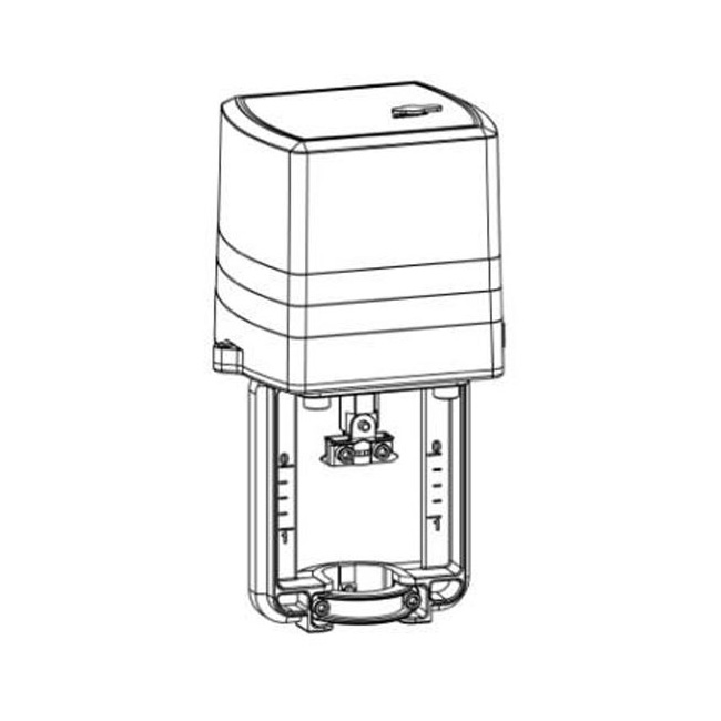
- Die-casting aluminum bracket and ABS cover
- Actuator can meet different pressure demand
- Synchronous motor, equip with shut power function, it can open at any position due to supply stable torque
- forward and reversal control setting meet different valve body
1. Reserve enough space for maintenance during installation.
2. The wiring shall comply with the national electrical construction specification, and conducted in the case of power off.
3. The actuator should not be covered by thermal insulation material to prevent it from heat dissipation.
4. Vertical installation should be given priority, and inclined or horizontal installation can be adopted in special occasions, but support and fixation should be added when the volume, weight and vibration are too large.
5. Manual valves are recommended to be installed at both ends of the control valve to facilitate maintenance. During use, grease should be added regularly for three or four months.
6. When the installation position of the control valve is not indicated on the design drawing, the control valve is generally installed on the return water pipe.
Installation Diagram of S6062A Control Valve Actuator
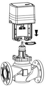
1. Insert the actuator into valve stem
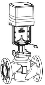
2. Tight two screws use hex key
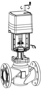
3. Use manual lever to adjust the stroke, then put gasket into slot, last tight the nut
Attention: the assemble must vertical between actuator and valve body
Dimension of S6062A Control Valve Actuator
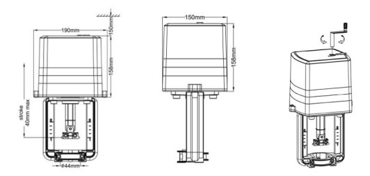
Manual Operation:
1. Insert handle
2. Rotate “UP” and “DOWN”.
Technical Parameter of S6062A Control Valve Actuator
| Item No. |
S6062A-DV |
S6062A-FV |
S6062A-MV |
| Voltage |
AC220±15% |
AC24V±15% |
AC24V±15% |
| Power |
16VA |
| Input Signal |
on off |
Floating |
0-10VDC/4-20mA |
| Feedback Signal |
——- |
—— |
0-10VDC/4-20mA |
| Act Speed(mm/s) |
0.20(50Hz) |
| Max. Stroke(mm) |
44mm |
| Output Force(N) |
2500/4000/5000 |
| End Connection |
Buckle |
| Height(mm) |
379 |
| Weight(kgs) |
4.7 |
Environment Temperature: -5℃~55℃ 2.Storage Temperature:-2℃~85℃ 3. Protect Class: IP 44

Modulating Wiring of S6062A Control Valve Actuator

The Manufacturer of HVAC Control Valves and Valve Actuators
The HVAC Actuator Valve Working Principle
HVAC Control Valves and Actuators
 SEARCH

